Control DMX Light Scenes via UDP
Central control system, interactive control software and touch control terminal have been widely used in museums, exhibition halls, cultural tourism lighting projects, sand tables and other similar environments. This kind of application requires unified control of sound, light, electricity and multimedia display screen to achieve immersive experience effect. Engineers can control the playback of multimedia files through code. For stage lights, special effect lights, LEDs, lifting balls, etc., especially for moving head lights with more than 20 channels, each channel has different functions. In this case, it will be extremely difficult to use the program code. It is better to program the lighting scene with the help of professional stage lighting software, download it to the stand alone controller, and then use the simple UDP code. It is easy to realize the linkage control of various equipment.
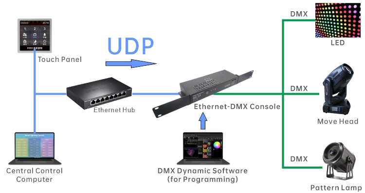
1. UDP-DMX Wire Diagram
2. Set Static IP Address
UDP central control, usually using a static IP address, to improve network performance. That is to say, we need to set a static IP for the ethernet DMX stand alone console, and then send a UDP command to this IP address through the central control host. To set a fixed IP address, you need to use software "Hardware Manager" you can download by clicking on the name.
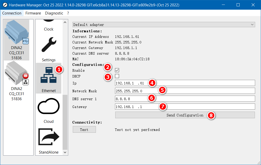
Before setting the static IP, connect the stand alone console to the computer using the USB cable and run "Hardware Manager".
- In the list of functions, select "Ethernet"
- Check "Enable", which is checked by default
- Cancel the DHCP option
- Input the static IP address. The IP address is required to be in the same network segment with the computer, tablet or scene panel (for example, 192.168.1.X network segment), but it shall not be duplicated or conflicted with the IP address of other devices.
- Network Mask: generally 255.255.255.0, which shall be consistent with other devices in the LAN
- DNS Server 1, no modification required
- Gateway: It is generally the first IP address of the network segment, such as 192.168.1.1
- After setting, click "Send Configuration" to save the network parameters
Note:
If you do not plug in the network cable to the stand alone console, the "Information" at the top of the settings window will not display the correct IP address. It will usually display "0.0.0.0".
3. Test the UDP Command
After setting up the mini stand alone console, you can use UDP-DMX Tool to send UDP commands to test system functionality. You can download the software by clicking on the name.
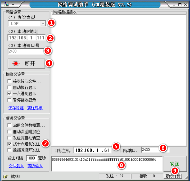
Network debugging assistant, easy to use, please refer to the following steps to use:
- Select the protocol type: UDP;
- Select/set the IP address of the local computer. If there are multiple network cards, you need to select the correct IP address;
- Enter the local port number: 2430;
- Click "Connect";
- Enter the IP address of the stand alone console;
- Enter the port number for the console: 2430;
- Select "Send as Hex";
- Enter the UDP command. You can also copy the UDP command from the code file;
- Click "Send", and the software will send UDP command
4. UDP Code Download
| UDP Code File (STICK-KE2) |
UDP Code File (STICK-DE3) |